KnowID: Knowledge-driven Information and Data access
Overview - EER-ARM transformations: the system - Publications and dissemination - Download - Contributors
Overview
Modern information systems require the orchestration of ontologies, conceptual data modelling techniques, and efficient data management in order to provide a way to better support informed decision-making and to ensure new requirements in organisational needs are met. A major issue to realise this, is to figure out which components to design and put together to realise the 'knowledge to data' pipeline, since each component and process has trade-offs. We introduce a new knowledge-to-data architecture, which we call KnowID. It combines both recently proposed components and adds novel transformation rules between (a logic-based representation of) EER diagrams as application ontology and the Abstract Relational Model to complete the pipeline. Compared to other ontology-based data access approaches, KnowID's key distinctive architectural features are that runtime use can avail of full SQL augmented with path queries, the closed world assumption commonly used in information systems, and avouds a costly mapping layer. Its architecture is sketched in Figure 1, below.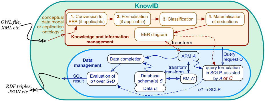
Figure 1. Overview of the KnowID architecture.
EER-ARM transformations: the system
A key component of the KnowID architecture is the transformation between EER and ARM. The transformation rules have been implemented recently and a basic interface added. The system itself has a modular architecture, which straightforwardly permits extension with other components of the KnowID architecture. A few screenshots are included below.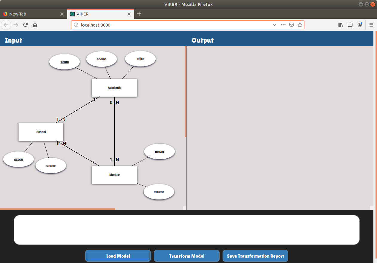
Figure 2. Screenshot after loading an EER diagram (serialised and stored as a JSON file).
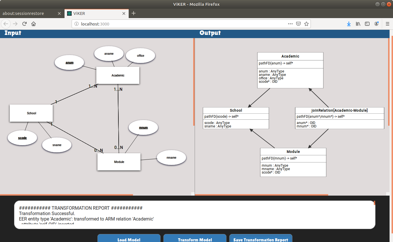
Figure 3. Screenshot of the state of the interface after transforming an EER diagram into an ARM model, with the ARM figure approximating the text-based specifications of the relations.
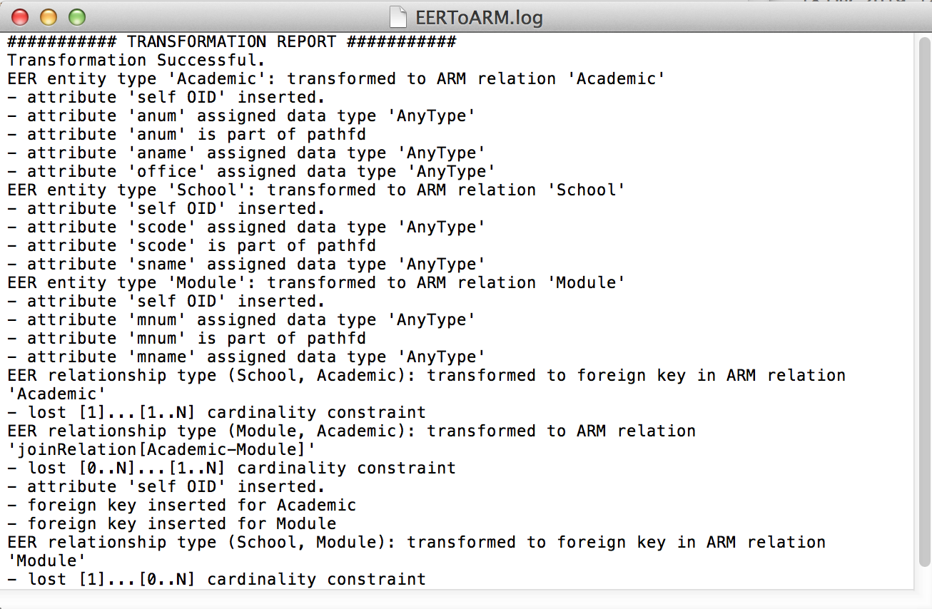
Figure 4. Screenshot of the complete logfile after transforming the EER diagram into an ARM model.
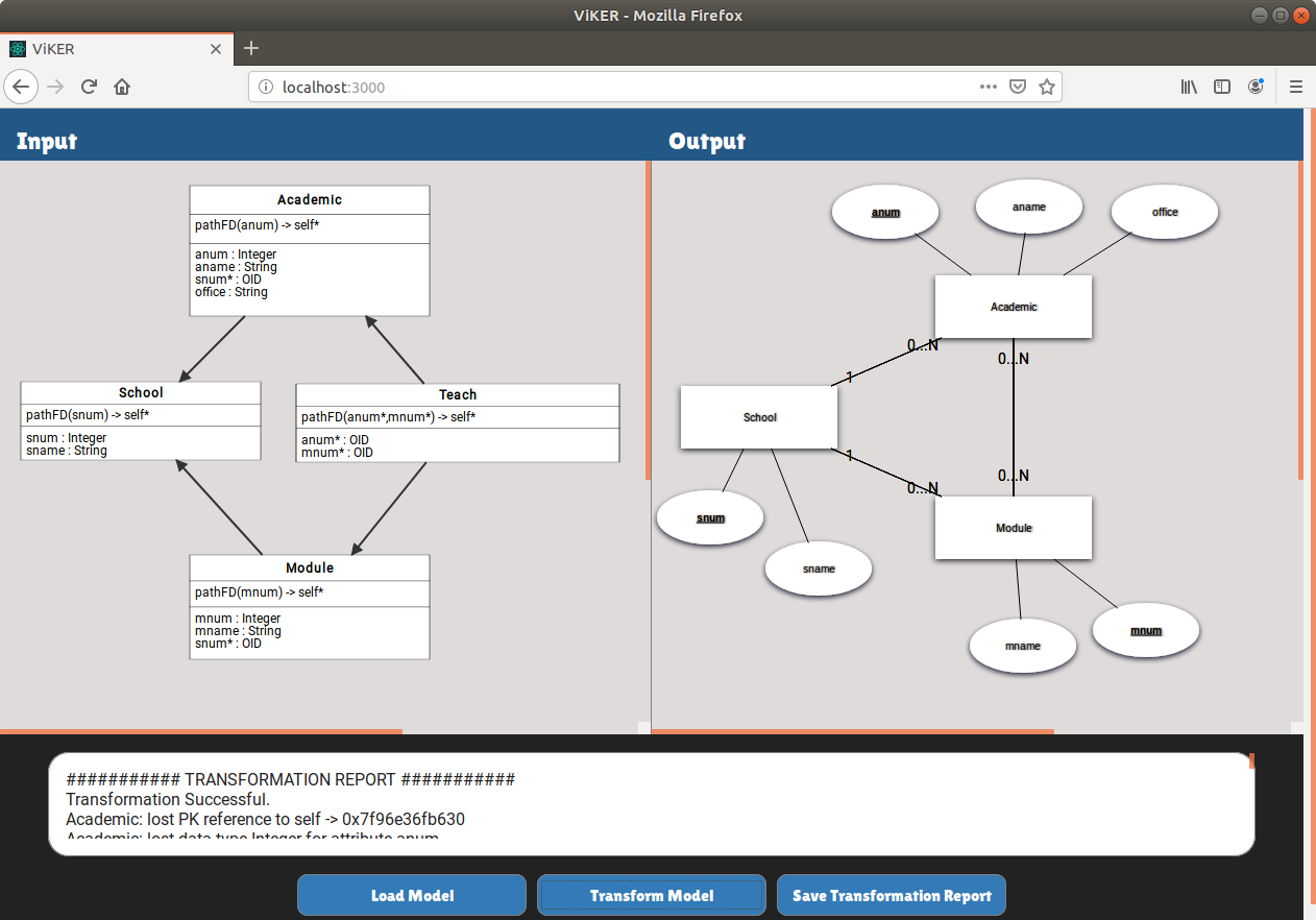
Figure 5. Screenshot of the state of the interface after transforming an ARM model into and EER diagram.

Figure 6. Screenshot of the complete logfile after transforming the ARM diagram into an ERD.
Publications and dissemination
- Publications:
- Fillottrani, P.R., Keet, C.M. KnowID: An architecture for efficient Knowledge-driven Information and Data access. Data Intelligence, 2020, 2(4): 487-512.
- KnowID supplementary material to the DI paper, which consists of this page at the time of publication of the article in late June 2020 (as early online access).
- Fillottrani, P.R., Jamieson, S., Keet, C.M. Connecting knowledge to data through transformations in KnowID: system description. Künstliche Intelligenz, 2020, 34, 373-379.
- Fillottrani, P.R., Keet, C.M. An architecture for efficient Knowledge-driven Information and Data access (Abstract). Forum on AI Research 2019 (FAIR'19), 4-6 December 2019, Cape Town, South Africa. CEUR-WS vol. 2540.
- Student projects:
- Mandisa Baleni: A Tool for managing the Materialization of Deductions in a Conceptual Data model (honours (4th-year) project report, UCT, 2020)
- Bradley Malgas: Visual Query Formulation: Generating SQLP queriesusing EER diagrams (honours (4th-year) project report, UCT, 2020)
- Knowledge-driven databases honours project website
Downloads
- Source code
- Examples and test cases: EER diagrams and ARM diagrams to load and transform
Contributors
- Maria Keet, University of Cape Town, South Africa
- Pablo Fillottrani, Universidad Nacional del Sur, Bahía Blanca, Argentina
- Stephan Jamieson, University of Cape Town, South Africa
- Mandisa Baleni and Bradley Malgas, University of Cape Town, South Africa (2020)
- Jeremy Du Plessis, St John Grimbly, and Gabriel Stein, University of Cape Town, South Africa (2019)